
Introduction
Did you ever felt the need for a cool RGB matrix with an audio reaction feature, but found it very difficult to make or very expensive to purchase? Well, now your wait is over. You can have a cool Audio Reactive RGB LED matrix in your room. This blog will guide you through the easiest steps to make a DIY RGB LED Matrix with cool effects & audio-reactive features. So, let's get started.
Step 1: What Will You Need?


All the material mentioned here is easily available in your local market as well as online stores.
Cardboard Sheet
Masking Tape
Maixduino Controller Board
WS2812b Addressable LED Strip
18 AWG Hookup Wire
Jumper Cables
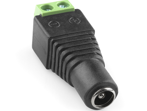
Female DC Power Jack
DC adapter 5 volt 10A (Optimal current required for full white is 9A)
Note: You will require all the accessories mentioned here. You can try out alternatives for any accessory as per your convenience except the Maixduino Board.
Step 2: Cutting & Marking the Cardboard


First, you need to cut your cardboard sheet in the size of 12 x 12 inches. This size is perfect for the LEDs as well as your room space.
Then you need to mark 10 points/holes on your cardboard with a pen/pencil/marker on top & bottom points to make guide markers for the LED strip & holes for the wires. You can place the LED strip on cardboard & mark on 1st LED & 15th LED (Follow the second image).
Step 3: Cutting & Sticking the LED Strip

The next step is to cut the LED Strip into 10 pieces. Each piece should be 15 Pixels/LEDs long.
Then stick the pieces on the cardboard with some adhesive glue. (Refer to the image).
Step 4: Making the Connections


There are few connections only, viz;
Refer to the connections from the circuit image.
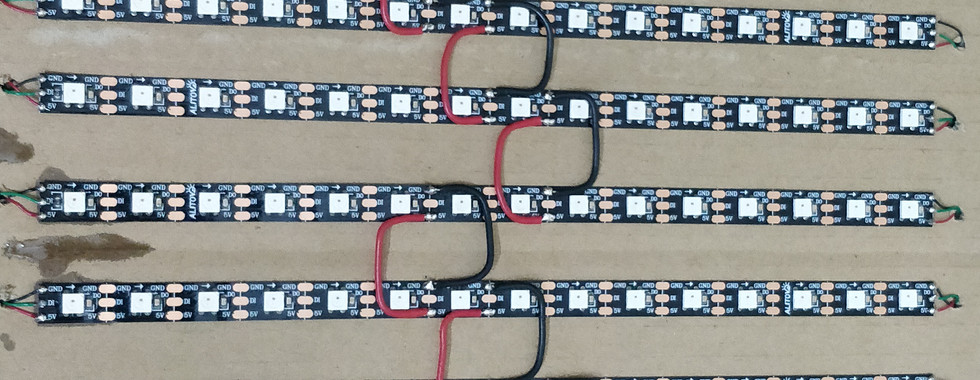
Connect GND/0V of each LED strip piece together
Connect VCC/+5V of each LED strip piece together
Connect Data Out of 15th LED in each strip piece to the Data In of 1st LED in the next strip.
Connect two wires for each Positive & Negative Connection & one wire for Data In of 1st LED of 1st strip.
At last, connect a Female DC jack to one pair of Positive & Negative wire for power injection.
Connect the Data In wire to Maixduino Pin #24 ( #24 is the digital pin 5 of Maixduino )
Connect another pair of Positive & Negative wire to Maixduino Vcc & GND.
General Precautionary Measures(Optional):
Stick masking tape on the backside of the cardboard to secure the connection wires. (Image 3).
Use a plastic tie to secure the input wires (Image 4).
Note: Double Check the connections before powering up the device.
Correction: The LED strip in the circuit image is 10 LED long, Please Consider it to be 15 LED long. Thanks for your cooperation.
Step 5: Let's Code It
Download the code attached & burn it in Maixduino.
Step 6: Turn on the Speakers & Enjoy Your Audio-Reactive LED Matrix

Comments